


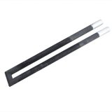
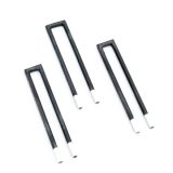
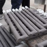


U-type silicon carbide heating elements consist of two straight rods connected by an end conductive bridge, forming a high-temperature resistive heater. They operate at up to 1625°C (in oxidizing atmospheres) and are ideal for side-wall installation in furnaces requiring U-shaped electrical loops without bent components. Widely used in pusher kilns and car-bottom furnaces due to their structural adaptability.
The U-type silicon carbide heating element is an integrated high-temperature resistor made from high-purity recrystallized SiC. Its two straight rods are connected by an end bridge, with customizable parameters (hot-end diameter, center spacing, hot/cold zone lengths, etc.) to suit diverse furnace layouts.
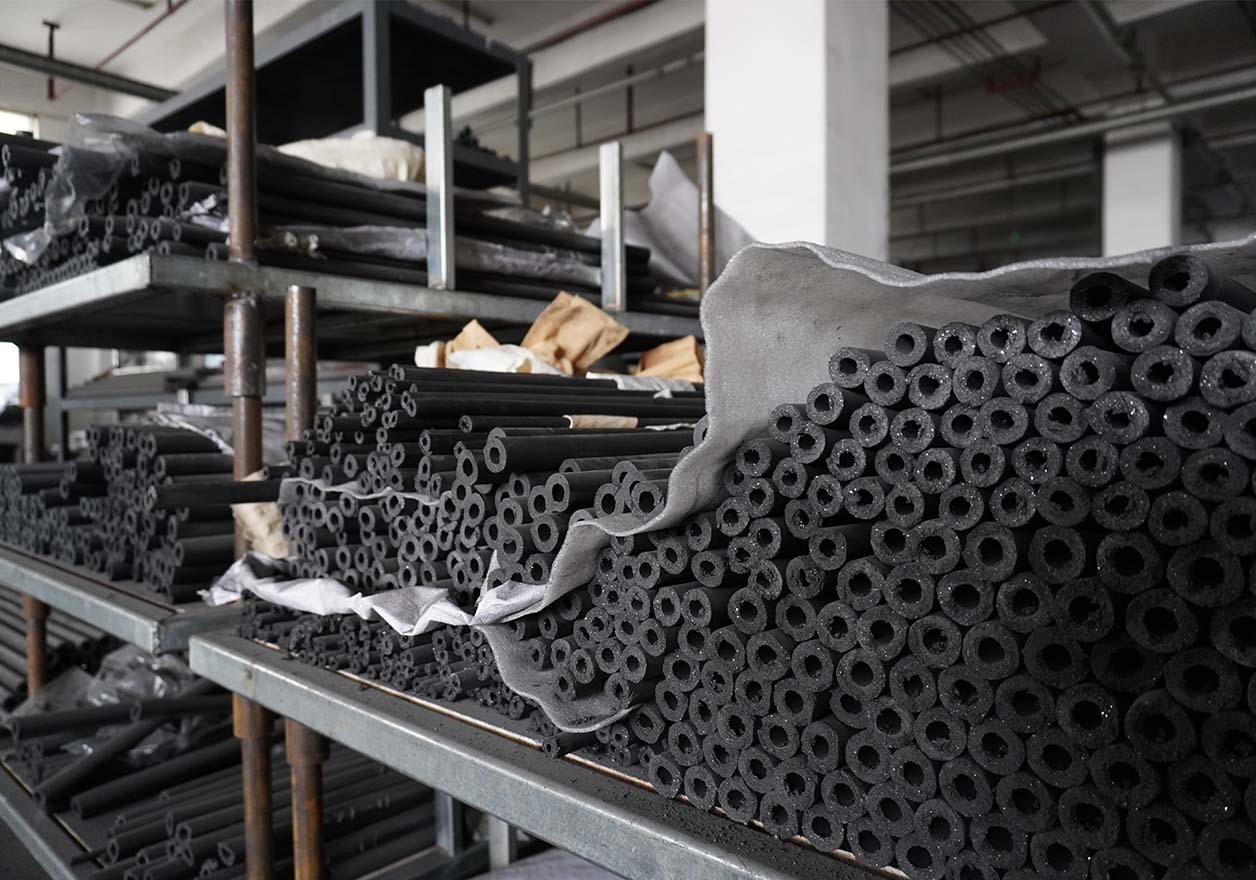
Operating at 1500°C in air, it offers high thermal radiation efficiency, thermal shock resistance, and stability for sintering and heat treatment in PV, ceramics, metallurgy, and glass industries
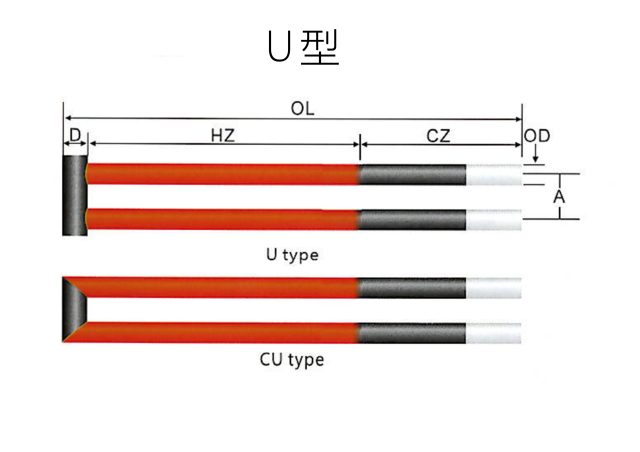
Product Structure Explanation:
Example: U-type, OD=16mm, OL=625mm, CZ=300mm, HZ=300mm, D=25mm, R=3.18Ω, denoted as U-625×300×16
Note: Contact us for other specifications or customization.
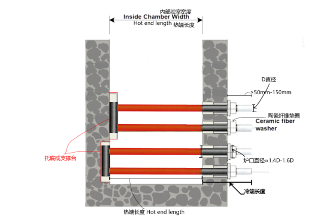
U-Type SiC Heating Element Configuration & Furnace Matching
| Number | Size | Hot Zone surface area | Nominal loading values* | Standard pin hole location*2 |
|||||
| External Diameter | Hot Zone Length | Cold End Length | Overall Length | ||||||
| mm | mm | mm | mm | cm² | Voltage | Power | Resistance | ||
| U-625*300*16 | 16 | 300 | 300 | 625 | 301 | 121 | 4600 | 3.18 | 40 |
| U-725*400*16 | 400 | 300 | 725 | 402 | 160 | 6080 | 4.21 | ||
| U-825*400*16 | 400 | 400 | 825 | 402 | 163 | 6190 | 4.29 | ||
| U-825*500*16 | 500 | 300 | 825 | 502 | 200 | 7600 | 5.26 | ||
| U-730*300*20 | 20 | 300 | 400 | 730 | 376 | 112 | 5990 | 2.09 | 45 |
| U-780*350*20 | 350 | 400 | 780 | 439 | 130 | 6960 | 2.43 | ||
| U-830*400*20 | 400 | 400 | 830 | 502 | 147 | 7860 | 2.75 | ||
| U-830*450*20 | 450 | 350 | 830 | 565 | 164 | 8770 | 3.07 | ||
| U-930*500*20 | 500 | 400 | 930 | 628 | 183 | 9790 | 3.42 | ||
| U-1030*500*20 | 500 | 500 | 1030 | 628 | 185 | 9900 | 3.46 | ||
| U-1030*600*20 | 600 | 400 | 1030 | 753 | 218 | 11700 | 4.06 | ||
| U-1130*600*20 | 600 | 500 | 1130 | 753 | 220 | 11800 | 4.1 | ||
| U-1130*700*20 | 700 | 400 | 1130 | 879 | 253 | 13500 | 4.74 | ||
| U-1230*700*20 | 700 | 500 | 1230 | 879 | 256 | 13700 | 4.78 | ||
| U-1230*800*20 | 800 | 400 | 1230 | 1005 | 289 | 15500 | 5.39 | ||
| U-1330*800*20 | 800 | 500 | 1330 | 1005 | 291 | 15600 | 5.43 | ||
| U-835*400*25 | 25 | 400 | 400 | 835 | 628 | 131 | 9370 | 1.83 | 55 |
| U-935*400*25 | 400 | 500 | 935 | 628 | 133 | 9510 | 1.86 | ||
| U-885*450*25 | 450 | 400 | 885 | 706 | 147 | 10500 | 2.06 | ||
| U-935*500*25 | 500 | 400 | 935 | 785 | 163 | 11700 | 2.27 | ||
| U-1035*500*25 | 500 | 500 | 1035 | 785 | 165 | 11800 | 2.31 | ||
| U-985*550*25 | 550 | 400 | 985 | 863 | 179 | 12800 | 2.5 | ||
| U-1035*600*25 | 600 | 400 | 1035 | 942 | 195 | 13900 | 2.74 | ||
| U-1135*600*25 | 600 | 500 | 1135 | 942 | 197 | 14100 | 2.75 | ||
| U-1135*700*25 | 700 | 400 | 1135 | 1099 | 227 | 16200 | 3.18 | ||
| U-1235*700*25 | 700 | 500 | 1235 | 1099 | 229 | 16400 | 3.2 | ||
| U-1235*800*25 | 800 | 400 | 1235 | 1256 | 259 | 18500 | 3.63 | ||
| U-1335*800*25 | 800 | 500 | 1335 | 1256 | 261 | 18700 | 3.64 | ||
| U-940*500*30 | 30 | 500 | 400 | 940 | 942 | 148 | 13800 | 1.59 | 55 |
| U-1040*500*30 | 500 | 500 | 1040 | 942 | 150 | 14000 | 1.61 | ||
| U-1040*600*30 | 600 | 400 | 1040 | 1130 | 177 | 16500 | 1.9 | ||
| U-1140*600*30 | 600 | 500 | 1140 | 1130 | 179 | 16700 | 1.92 | ||
| U-1140*700*30 | 700 | 400 | 1140 | 1319 | 206 | 19300 | 2.2 | ||
| U-1240*700*30 | 700 | 500 | 1240 | 1319 | 208 | 19400 | 2.23 | ||
| U-1240*800*30 | 800 | 400 | 1240 | 1507 | 235 | 22000 | 2.51 | ||
| U-1340*800*30 | 800 | 500 | 1340 | 1507 | 237 | 22200 | 2.53 | ||
| U-1340*900*30 | 900 | 400 | 1340 | 1696 | 264 | 24700 | 2.82 | ||
| U-1440*900*30 | 900 | 500 | 1440 | 1696 | 266 | 24900 | 2.84 | ||
| U-1540*1000*30 | 1000 | 500 | 1540 | 1884 | 295 | 27600 | 3.15 | ||
| U-1045*600*35 | 35 | 600 | 400 | 1045 | 1319 | 179 | 19200 | 1.67 | 60 |
| U-1145*600*35 | 600 | 500 | 1145 | 1319 | 181 | 19400 | 1.69 | ||
| U-1145*700*35 | 700 | 400 | 1145 | 1539 | 209 | 22400 | 1.95 | ||
| U-1245*700*35 | 700 | 500 | 1245 | 1539 | 211 | 22600 | 1.97 | ||
| U-1245*800*35 | 800 | 400 | 1245 | 1759 | 239 | 25600 | 2.23 | ||
| U-1345*800*35 | 800 | 500 | 1345 | 1759 | 240 | 25700 | 2.24 | ||
| U-1345*900*35 | 900 | 400 | 1345 | 1979 | 269 | 28800 | 2.51 | ||
| U-1445*900*35 | 900 | 500 | 1445 | 1979 | 270 | 28900 | 2.52 | ||
| U-1545*1000*35 | 1000 | 500 | 1545 | 2199 | 300 | 32100 | 2.8 | ||
Nominal load values measured at 1000°C in open air. Convert to current, tolerance is ±15% of center value.
Select a suitable rod model from the table above based on your application. Contact us for free samples if interested.
Crossbar size
| D(External Diameter) | 16 | 20 | 25 | 30 | 35 |
| D0(Link Bridge Outer Diameter) | 25 | 30 | 35 | 40 | 45 |
| H(Link Bridge Length) | 76 | 90 | 110 | 125 | 140 |
Reviews
There are no reviews yet.